

If you’ve been sourcing metal parts long enough, you’ve already been through the argument: additive versus subtractive. The reality that most application engineers arrive at — usually after a failed prototype or a blown budget — is that the question itself is wrong. The right question is, where in the workflow does each process earn its place?
Metal additive manufacturing (AM), particularly Selective Laser Melting (SLM 3D printing) and Direct Metal Laser Sintering (DMLS), has matured to the point where it genuinely competes with CNC machining on specific feature classes. But “competes” doesn’t mean “replaces.” Understanding the precise boundary between the two is where serious design engineers find real cost and performance leverage.
This article breaks down how to structure a hybrid metal AM + CNC workflow, where tolerance and surface finish requirements force the decision, and which material-process combinations make economic sense at Hyperlab3d’s production scale.

Why Hybrid Isn’t a Compromise — It’s a Strategy
The word “hybrid” tends to make procurement teams nervous. It sounds like a workaround. It isn’t.
Hybrid manufacturing — printing a near-net-shape blank via SLM or DMLS, then finishing critical surfaces on a CNC machining center — is the standard workflow for aerospace brackets, medical implants, and hydraulic manifolds precisely because it allocates each process to what it does best:
- Metal AM handles geometric complexity: Internal lattices, conformal cooling channels, topology-optimized structures, and undercuts that would require five-axis contortion or wire EDM to machine conventionally.
- CNC machining handles dimensional precision: Bearing bores, thread features, sealing surfaces, and any interface requiring tolerances tighter than ±0.1 mm — the practical floor for most SLM processes on as-built surfaces.
The efficiency gain is real. A conventionally machined titanium bracket starts from billet, meaning you’re buying and then milling away 60–80% of the raw material. The same part printed near-net loses maybe 5–15% in post-machining. For Ti-6Al-4V at current material costs, that’s not an incremental saving — it’s a project-level budget line.
Understanding As-Built Tolerances in SLM 3D Printing
Before designing for hybrid workflow, you need honest numbers on what SLM and DMLS actually deliver off the build plate — not vendor marketing figures, but the values you should design to.
Dimensional Accuracy: What to Expect
| Process | Typical As-Built Tolerance | Practical Design Tolerance |
|---|---|---|
| SLM (Stainless 316L, Ti-6Al-4V) | ±0.1–0.2 mm | ±0.2 mm with design compensation |
| DMLS (Inconel 625, AlSi10Mg) | ±0.05–0.15 mm | ±0.15 mm on controlled geometries |
| DMLS (Cobalt Chrome) | ±0.05–0.1 mm | ±0.1 mm on flat surfaces |
These numbers hold on well-supported, medium-complexity geometries under 200 mm. Tall, thin-walled features, large flat sections, and overhanging masses all introduce residual stress and thermal distortion that push you toward the worse end of those ranges — or beyond them.
The practical rule: design any as-built surface that requires fit, function, or sealing to ±0.5 mm, and plan CNC finishing for anything tighter. Designing to the theoretical tolerance floor is how engineers end up in dimensional disputes with their machine shop.
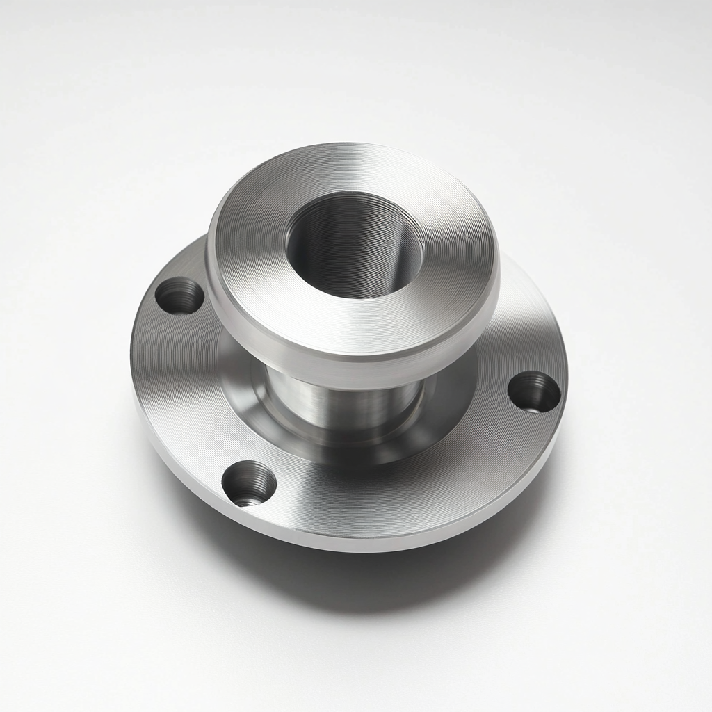
Surface Roughness: The Finish You Actually Get
As-built SLM surfaces typically land in the Ra 10–25 µm range depending on orientation, laser parameters, and material. Downward-facing surfaces are consistently worse than upward-facing ones due to support contact and heat accumulation.
For reference:
– Ra 10–25 µm (as-built AM): Acceptable for non-sealing, non-wear, non-cosmetic surfaces
– Ra 1.6–3.2 µm: Achievable with post-processing (shot peening, electropolishing, vibratory finishing)
– Ra 0.8 µm and below: Requires CNC finish machining or grinding
If you’re designing a hydraulic manifold with O-ring grooves, a turbine bracket with bearing interfaces, or any part with threaded inserts, those features need CNC finishing. Print them oversized and machine to final dimension.
Material Selection for Metal AM: The Real Constraints
Material selection in metal additive manufacturing involves constraints that don’t exist in conventional machining, and ignoring them is the most common source of project-scope creep.
Titanium (Ti-6Al-4V ELI)
The workhorse of aerospace and medical AM. Excellent strength-to-weight ratio, biocompatible in ELI grade, and well-characterized under SLM/DMLS parameters. Key constraints:
- Residual stress is significant: Ti-6Al-4V builds up substantial internal stress during printing. Stress relief heat treatment before removal from the build plate is not optional for structural parts — it’s the step that determines whether your part distorts on the wire EDM.
- Post-machining behavior: Titanium work-hardens aggressively. Your CNC parameters for printed titanium need to be dialed differently from billet — lower cutting speeds, higher feed rates, rigid fixturing.
Stainless Steel (316L, 17-4 PH)
316L prints reliably and offers good corrosion resistance. 17-4 PH in H900 condition reaches tensile strengths exceeding 1300 MPa after age hardening — comparable to many aerospace-grade steels at significantly lower density.
One frequently underestimated variable: printed 316L is not identical to wrought 316L. Microstructure differs. If your application involves cyclic fatigue loading or cryogenic service, you need coupon testing from the same build parameters as your production parts, not literature values from wrought material.
Inconel 625 and 718
When you’re operating above 600°C or in aggressive corrosive environments, nickel superalloys are the answer. Inconel 625 is weldable and corrosion-resistant; IN718 offers higher strength with precipitation hardening.
The manufacturing reality: Inconel is slow to print (dense, reflective, thermally demanding), expensive per kilogram, and punishing to machine. Hybrid workflows make the most economic sense here — print the complex geometry, machine only the surfaces that need it, and avoid removing any more Inconel than necessary.
Aluminum (AlSi10Mg, Scalmalloy)
AlSi10Mg is the accessible aluminum alloy for SLM — reasonable cost, decent mechanical properties, good printability. Scalmalloy is the high-performance option: higher strength, better ductility, comparable to 6061-T6 in many load cases.
The critical limitation: aluminum reflects laser energy and conducts heat rapidly, making it more sensitive to parameter variation than titanium or steel. Part quality consistency requires tighter process control and more conservative design rules (minimum wall thickness ≥ 1.0 mm, preferably 1.5 mm for structural walls).
Where CNC Machining Still Owns the Problem
Hybrid workflows are not the answer to every problem. There are application categories where SLM 3D printing adds cost and complexity without adding value and where CNC machining from billet remains the right call:
Simple prismatic geometry with tight tolerances: If your part is essentially a block with holes, slots, and threads, CNC machining will always be faster and cheaper. Additive manufacturing’s geometric freedom is irrelevant if you’re not using it.
High-volume production of stable designs: For parts you’re running in the thousands with no geometry changes on the horizon, the per-unit economics of CNC or injection molding typically win. AM’s advantage is in low-to-medium volumes, design iteration, and complexity.
Extremely tight tolerances throughout: If the entire part needs ±0.025 mm, you’re machining the whole thing. AM as a roughing step doesn’t help if every surface requires finishing.
Hard, difficult-to-weld alloys that don’t print well: Some materials (certain tool steels, dispersion-hardened alloys) are either not available as qualified AM powders or have process challenges that outweigh the geometric benefits.
Designing for Hybrid: Practical Rules That Save Rework
Getting a hybrid part right the first time requires building post-machining into the design from the beginning — not treating it as an afterthought.
Add Machining Stock on Critical Surfaces
Any surface that will be CNC finished needs material to remove. Standard practice:
- Sealing faces, bearing interfaces: +0.5–1.0 mm stock
- Threaded bores: Print undersized and drill/tap to final dimension (threading printed material directly is unreliable)
- Press-fit features: +0.3–0.5 mm stock minimum
Don’t rely on the print hitting nominal and then skimming a few microns — you’ll lose the feature on a bad build.
Datum and Fixturing Features
Your machinist needs to clamp and locate the printed blank. If your part doesn’t have clear, accessible datum surfaces, your CNC operator is going to improvise — and that’s how you get positional error between the printed features and the machined ones.
Design dedicated fixture pads into the build if the part geometry doesn’t provide natural datums. They add a few grams and can be machined off in the finishing operation.
Orientation Governs Everything
Build orientation in SLM affects:
– Dimensional accuracy (different axes have different shrinkage behavior)
– Surface roughness (downward-facing surfaces are roughest)
– Anisotropic mechanical properties (load-bearing features should align with build direction for best fatigue performance)
– Support volume and removal difficulty
The orientation that minimizes supports is often not the orientation that optimizes mechanical performance or surface quality on critical faces. Decide which constraint drives the build, and document it so downstream processes know what to expect.
Quality Validation in Hybrid Metal AM Parts
Inspection strategy for hybrid parts differs from either pure-AM or pure-machined parts because you have two sources of geometric error that interact.
Post-print, pre-machining inspection: Confirm that the as-built blank has sufficient machining stock everywhere it needs it. A CMM scan at this stage catches distortion before it costs you machining time. For complex internal geometries, CT scanning is the only non-destructive method that gives you full dimensional data.
Post-machining final inspection: Standard CMM protocol on all machined features. Surface roughness measurement on sealing and bearing surfaces.
Material validation: For structural and safety-critical applications, witness coupons printed in the same build as the production parts are the minimum. These get pulled for tensile, hardness, and where relevant, fatigue testing. Literature mechanical properties are starting points, not acceptance criteria.
The Hyperlab3d Approach: Where We Add Value in Hybrid Workflows
At Hyperlab3d, our SLM 3D printing capability is built around this exact workflow — not standalone printing, but metal AM as the front end of a production process that includes in-house CNC finishing, heat treatment coordination, and dimensional validation.
We routinely handle:
– Ti-6Al-4V aerospace structural components with ±0.05 mm machined features
– Inconel 625 high-temperature manifolds with conformal internal geometry
– 316L stainless tooling and fixtures where additive geometry reduces weight and lead time versus billet
If you’re working on a part where the geometry would be expensive to machine conventionally but the tolerances demand a machined finish on key interfaces, that’s the exact application profile hybrid manufacturing was built for.
Conclusion: Matching Process to Problem in Metal AM
The engineering value of SLM 3D printing and DMLS is most accessible when you approach them as tools with specific strengths and defined limits — not as a universal replacement for conventional manufacturing.
Hybrid metal AM + CNC workflows deliver the best outcomes when:
– Geometric complexity is high (internal channels, topology optimization, organic surfaces)
– Material efficiency matters (expensive alloys, billet removal ratios above 50%)
– Tolerances on critical features are tighter than ±0.1 mm
– Lead time on tooling or fixturing for conventional machining is a constraint
The design discipline required — machining stock on critical surfaces, explicit datum strategy, build orientation optimized for the primary mechanical load path — is what separates successful hybrid parts from expensive failures.
If you’re evaluating a metal component for SLM 3D printing and want a technical assessment of where additive manufacturing fits your specific geometry and tolerance requirements, contact Hyperlab3d’s engineering team. We’ll give you a straight answer on whether printing makes sense, what the hybrid workflow looks like, and what the real cost comparison looks like against conventional alternatives.
Meta Description: Hybrid metal AM + CNC machining explained for engineers. Learn SLM 3D printing tolerances, material selection (Ti-6Al-4V, Inconel, 316L), and design rules for hybrid workflows.